INSTRUCTION SET #1
The
first instruction set is the simplest of the four. The upside to this design is that it does not
require as much work as the other three designs, allowing you to finish it
quicker. If you want to just try it out
and do not care about the quality of the design, this is the instruction set
for you. This will also work well for
those who are not craftsman-inclined.
If
you have purchased other TV projection designs from eBay sellers, you will
notice quickly that these four instruction sets are higher quality than at
least 3 of the 4 designs in other plans.
We actually use bolts, staples, and glue to put our projectors
together. Most other plans use
tape. It is true, duct tape can fix
about anything, but we believe that our customers would probably prefer a
little higher quality in their projector.
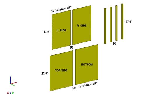
PARTS IDENTIFICATION
On this page, there are two "Purchase Lists" for your convience, one for Menards and one for Home Depot.
TOOLS IDENTIFICATION
PURCHASE LIST
(The below is the list
of parts for a 13" - 25" TV sized TV.
If your TV is larger, you might need more.)
Menards:
·
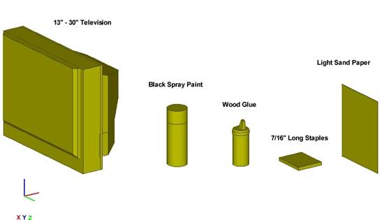
15" -
22" Television N/A
·
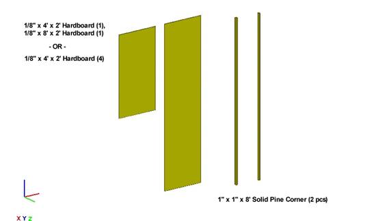
1/8 IN x 2 FT x 4
FT Hardboard (4 pcs)
or 1/8 IN x 2 FT
x 4 FT (1 pc) & 1 pc @ 8 FT Lumber
Section - mid-left side bldg
·
1 IN x 1 IN x 8 FT
Solid Pine Corner (2 pcs) Trim Section - back-left side bldg
·
Black Spray Paint (3 cans) Paint Section - back-right side of
bldg
·
Light Sand Paper
(1 pckg) Paint
Section - back-right side of
bldg
·
Wood Glue (1
bottle) Hardware
Section - front in 3rd row
·
Staples 7/16 Heavy Fastener
Section - middle of building
Home Depot:
·
15" -
22" Television N/A
·
1/8 IN x 2 FT x 4
FT board (4 pcs) Plywood
Lane - reg #1, right side bldg
·
1 IN x 1 IN x 8 FT
Solid Pine Corner (2 pcs) Plywood Lane - reg #1, right side
bldg
·
Black Spray Paint (3 cans) Paint Section - left side bldg
·
Light Sand Paper
(1 pckg) Near
Paint Section -reg #9, Door Sect
·
Wood Glue (1
bottle) Near
Paint Section - reg #9
·
Staples 7/16 Heavy Fastener
Section