INSTRUCTION SET #2
This
second instruction set is the standard design using wood for material. This design requires more work than the
first, but it is also higher quality. If
you want make your projector in the standard format without spending much more
money, this is the instruction set for you.
If
you have purchased other TV projection designs from eBay sellers, you will
notice quickly that these four instruction sets are higher quality than at
least 3 of the 4 designs in other plans.
We actually use bolts, staples, and glue to put our projectors
together. Most other plans use tape. It is true, duct tape can fix about anything,
but we believe that our customers would probably prefer a little higher quality
in their projector.
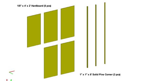
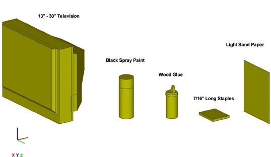
PARTS IDENTIFICATION
On this page, there are two "Purchase Lists" for your convience, one for Menards and one for Home Depot.
TOOLS IDENTIFICATION
PURCHASE LIST
(The below is the list
of parts for a 15" - 22" TV sized TV.
If your TV is larger, you might need to purchase large sized wood
pieces.)
Menards:
·
15" -
22" Television N/A
·
1/8 IN x 2 FT x 4
FT Hardboard (5 pcs) Lumber
Section -mid-left side of bldg
·
1 IN x 1 IN x 8 FT
Solid Pine Corner (3 pcs) Trim Section - back-left side of bldg
·
Black Spray Paint (3 cans) Paint Section - back-right side of
bldg
·
Light Sand Paper
(1 pckg) Paint
Section - back-right side of
bldg
·
Wood Glue (1
bottle) Hardware
Section -3rd row front bldg
·
Staples 7/16 Heavy Fastener
Section - middle of building
Home Depot:
·
15" -
22" Television N/A
·
1/8 IN x 2 FT x 4
FT board (5 pcs) Plywood
Lane - reg #1, right side bldg
·
1 IN x 1 IN x 8 FT
Solid Pine Corner (3 pcs) Plywood Lane - reg #1, right side
bldg
·
Black Spray Paint (3 cans) Paint Section - left side of bldg
·
Light Sand Paper
(1 pckg) Near
Paint Section -reg #9, Door Sect
·
Wood Glue (1
bottle) Near
Paint Section - reg #9
·
Staples 7/16 Heavy Fastener
Section
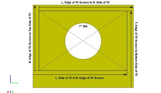
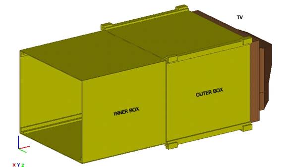
STEP #1
(Outer Box)
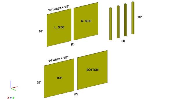
Cut the ply and corners to the
above measurements. NOTE: The 1/8" is the thickness of the ply sheets.
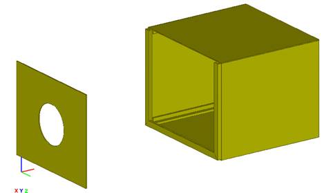
STEP #2
(Outer Box)
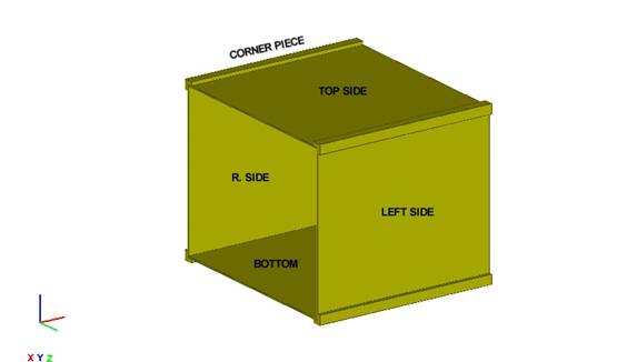
First, glue Bottom Panel and its two corner pieces together. Next, staple the panels to the corner pieces for extra strength. Do this same procedure with the Top Panel. Now, stand the assembled top and bottom and attach the side panels with glue and staples also.
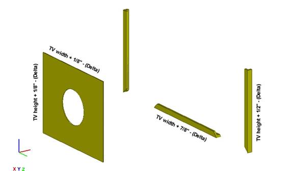
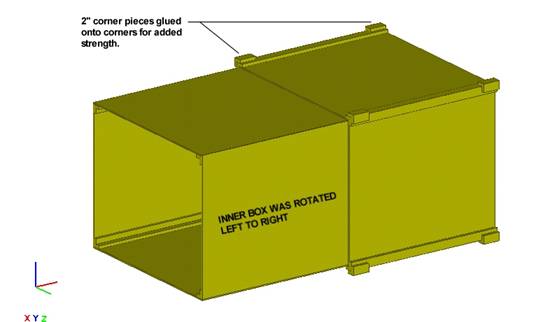
STEP #3
(Inner Box)
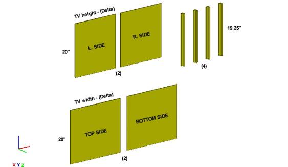
Cut the ply and corners to the above measurements for the inner box also. Delta is the tolerance between the Inner and Outer Box. In other words, Delta is the margin of error. NOTE: The 19.25" = 20 - (the width of the inner length on the corner pieces).
STEP #4
(Inner Box)
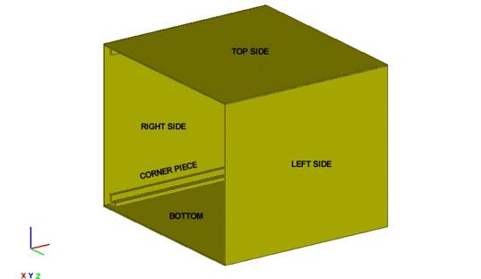
First, glue Bottom Panel and its two corner pieces together. Next, staple the panels to the corner pieces for extra strength. Do this same procedure with the Top Panel. Now, stand the assembled top and bottom and attach the side panels with glue and staples also.